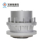


Pump Drives
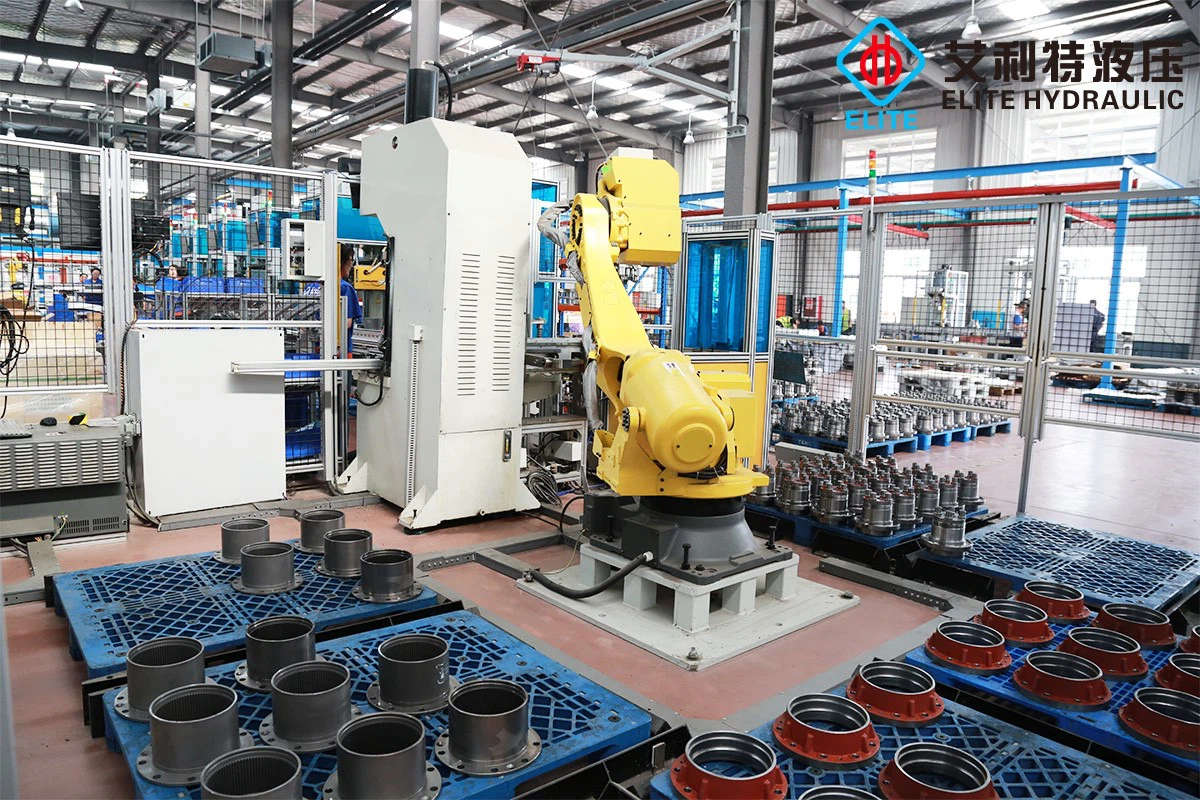
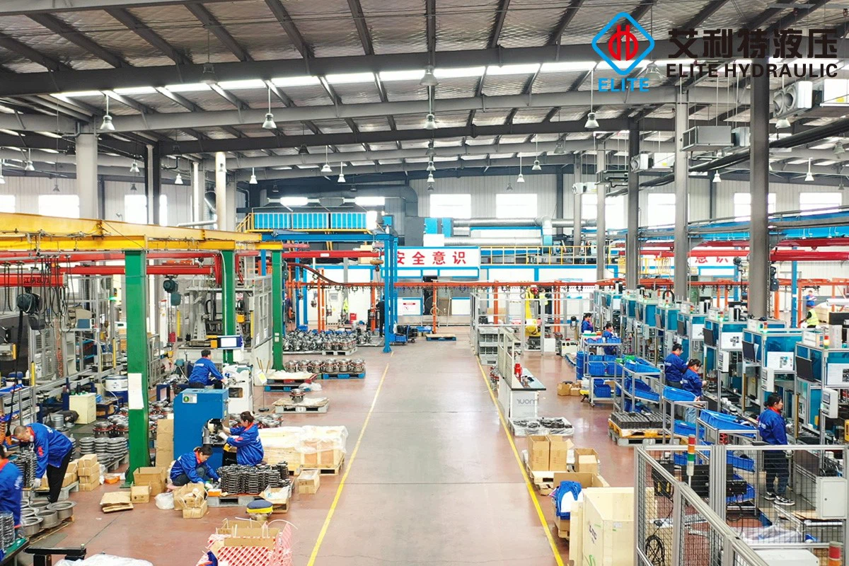
Qingdao Elite Hydraulic Co.,Ltd was founded in 2004 . Starting from the production of power transmission component parts for European and American customers.we have evolved into an established drivetrain manufacturer.providing product solution for modern powertrains of mechanical, hydrostatic, or electrically driven designs.
We manufacture and supply high quality travel drives,slewing drives,winch drives,cutter drives,transit mixer drives,twin shaft mixer drives ,pump drives,multiple disc brake,axle,machine tools spindle gearbox,and custom drivetrain systerms for both on and off highway markets and finding application in agriculture, forestry,construction,mining,concrete, AWP,airport ,marine & offshore,wind,machine Tools and special vehicles.
Why Choose Us
Professional Team
We have a strong R&D team,and we can develop and produce products according to the drawings or samples the customers offered.
Advanced Equipment
We have our own testing lab and the most advanced and complete inspection equipment,which can ensure the quality of the products.
Rich Experience
We focus on developing high-quality products for top-end markets.Our products are in line with international standards,and are mainly exported to Europe, America, and other destinations around the world.
Certificate
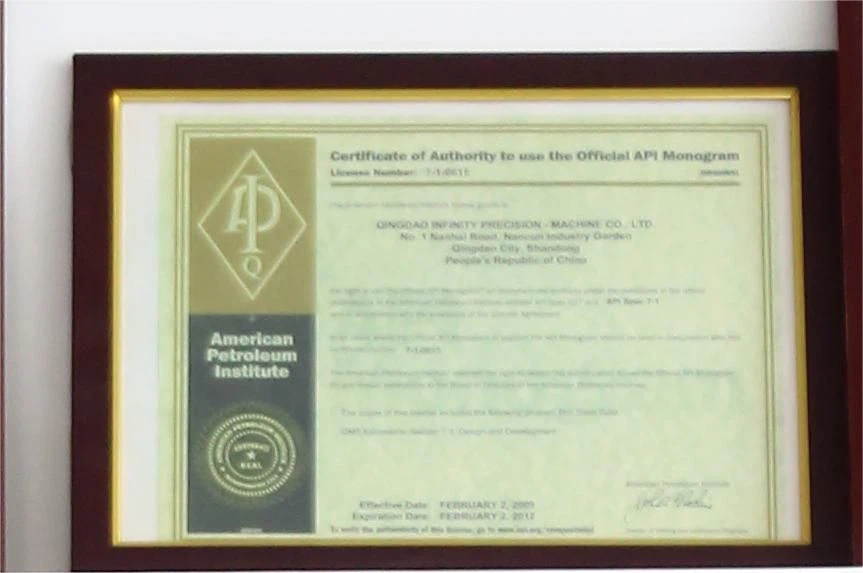
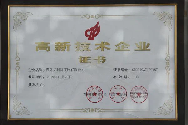
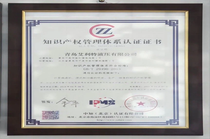
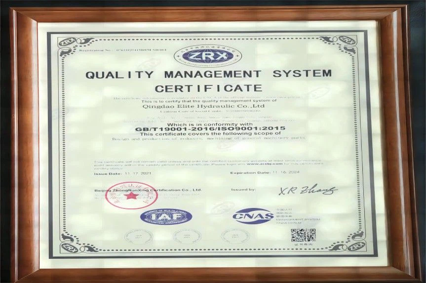
Our company has a complete organizational structure and quality management system, and has successively passed three major system certifications: ISO9001,IATF16949, and ISO14001.


What is Pump Drives?
Pump drives take power from an input rotational source and send it to a hydraulic pump. Gears or other equipment generate the power. Pumps are positioned on the drive housing.
A pump system's rotary power source is referred to as a drive. The term drive signifies motor control units such as an inverter or starter. It also refers to other segments of the power supply such as a motor or gearbox. Gearboxes moderate motor speed. When attached to a motor as a unit, they are considered gearmotors.
In its most basic form, a pump drive is a simple gearbox that is placed between an engine or electric motor and a system's hydraulic pump(s) to provide a way to couple them.
Benefits of Pump Drives
Mechanical seal replacement in pumps can impact operations through costs, labor, and downtime, potentially causing production delays and affecting the bottom line. Emergency maintenance can exacerbate disruptions and costs, including customer dissatisfaction and safety hazards. With their innovative design, however, Pump Drives eliminate the need for mechanical seals and provide a hermetic seal by removing the direct connection between the motor shaft and the impeller assembly. It excludes potential leak points and eradicates the need for seal replacements, which reduces costs and labor over the pump's lifespan and ultimately benefits the bottom line.
Pump Drives frequently facilitate the transfer of hazardous chemicals in various fluid-handling applications. Leaks in other conventional pumps can pose a significant threat to workers by exposing them to these dangerous substances. Such exposure can occur abruptly due to a substantial leak or gradually by releasing liquid or vapors from a compromised seal.
A principal reason for pump malfunction is operating without fluid, often resulting from human errors or system disturbances. In such situations, pumps may continue to function with no fluid, which leads to rapid deterioration or destruction of the pump in many instances. Nevertheless, specific mag-drive pump configurations can withstand dry operation. In industrial settings where pumps do not receive continuous monitoring, this capability to function without fluid can expressively reduce the likelihood of pump breakdowns and related expenses.
Magnetic drive pump technology demonstrates an exceptional ability to endure highly corrosive and dangerous liquids. These pumps' robustness makes them appropriate for handling highly corrosive scenarios where other pump designs may falter. Due to their impressive durability, mag-drive pumps can manage fluids that overwhelm alternative pumping systems. As a result, these pumps provide a flexible solution for demanding tasks needing resilient responses.
Selecting the appropriate pump can be a complicated task. Numerous elements must be considered to determine the right pump for the intended use, and incorporating various seal alternatives (such as seal design, elastomer choices, and seal components) further complicates the decision-making process. However, Pump Drives streamline the pump selection procedure.
Type of Pump Drives
Durst Pump Drives
Durst pump drives are built with a patented pump pad design that keeps the oil flowing continually through the bearing, lubricating the spline adapters even without external pumps. Durst pumps also use a four-disk drive plate, resulting in higher absorption of engine vibrations and a longer gearbox lifespan.
Cotta Pump Drives
At The Gear Centre Off-Highway Division, you can find Cotta pump drives that will suit even the most severe application. You can choose from 2, 3 or 4 station configuration, or even special purpose units, with 8 or more stations.
Funk Pump Drives
Funk pump drives are known in the industry for their proven performance, durability and cost efficiency. With 5,000 different configurations, you have a choice of horsepower, torque, gear ratio, pump adapters and mounting options to match your exact specifications. Funk pump drives offer a wide range of horsepower input, from 101 to 708 hp, and can operate from either an independent mount, a direct engine mount or as a clutch-driven unit.
Application of Pump Drives
Once the instrument's horsepower and rpm have been identified, the speed reducer service is selected. The speed reducer is required to have a service factor equal to or greater than the level recommended by the AGMA. Speed reducers with service factors unsuited to specific tasks are subject to premature failure.
With improvements in technology, drives using variable frequency inverters are gaining popularity. They replace belt cases and traction drives in activities where multiple speed operation is essential. They offer specific benefits such as programming and reliability. Use of standardized speed reducers and motors makes the devices more compact than belt cases or traction drives.
Torque analysis is helpful in minimizing the chances of over- or undersizing a drive's horsepower. Functions engaging dissimilar products with different rates of flow require variable torque. On the other hand, activities involving the same pump necessitate individually calculated torque. In these cases, the drive is sized to accommodate the largest torque and the greatest speed.

Selecting The Correct Pump Drive For The Job
Coupling direct connection: This transmission method is generally represented by the letter DC. This transmission method means that the motor and the slurry pump are directly connected by a coupling. Common couplings include claw couplings, pin couplings, and diaphragm couplings. The pump factory will select the appropriate coupling according to the matching motor power.
Belt connection: This transmission method means that the motor transmits the power to the slurry pump through the pulley and the belt. Belt connection is divided into CV transmission, CRZ transmission, CLZ transmission, ZVZ transmission, four transmission modes. The difference between these four transmission modes is that the arrangement of the pump and the motor is different.
CV transmission: In this transmission mode, the motor is installed above the bearing assembly of the pump. The pump and the motor do not have a common base, and the motor is installed by bolting a small seat of the motor. The characteristic of this transmission mode is that the installation of the pump and motor is relatively compact, which saves space and is suitable for use in limited working conditions. Since the motor is above, it can also avoid water entering the motor and causing damage to the motor. However, if the motor power is relatively large, this transmission method is not recommended. Because the power of the motor is large, its weight is relatively heavy. If this installation method is used, it may not be very stable, and it will appear top-heavy. Therefore, this transmission method is generally only recommended for use with low-power motors.
CRZ and CLZ transmission: This type of transmission means that the motor is installed on the left or right side of the pump. Viewed from the inlet direction of the pump, if the motor is on the left side of the pump, it is CL transmission, and if the motor is on the right side of the pump, then It is a CR drive. If the pump and motor have a common base, the letter “Z” means. But for a large pump, because of its own weight and volume, in this case, a common base is generally no longer provided. The feature of this installation method is that it runs relatively smoothly because it is installed on the ground. But it will take up a lot of space.
ZVZ transmission: This transmission method is the same as the CV transmission, in which the motor is placed at a high position. The difference is that this transmission method has a common base, the motor is directly behind the pump, and the purpose of the motor is achieved by raising the base of the motor. Because the orientation of the motor and pump in this transmission method looks like a capital letter “Z”, it is called ZVZ transmission. Since the motor is in a high position, if there is water leakage on site, the motor can be prevented from entering water, thereby protecting the motor. There is no limit to the size of the motor power, regardless of the size of the pump and motor, this transmission method can be used.
1. Number and type of pumps required
Each project will require a varying number and types of pump, depending on the needs of the project, the medium that is being pumped and the pump specifications. This will impact the amount of power that is needed to operate the application and ensure the pump will consistently meet the requirements for sustained operations.
2. Sizing the drive
The size of the drive will differ depending on whether a diesel engine or electric motor is being used. Sizing calculations are often determined by computer programs or graphs, as electric motors develop a very high starting torque, whereas the starting torque for diesel and gas engines remains relatively consistent.
3. Horsepower rating
Calculating the horsepower rating is important for determining the torque of the driver, and will influence a range of other factors when deciding on the appropriate pump drive. Horsepower can be calculated with specific computer programs or graphs. An excessive RPM could cause a gap between the expected and actual horsepower, meaning that the operational efficiency is reduced.
4. Speed
In addition to these factors, maximum input speed should be examined to make sure that the pump can accept the maximum input speed of the motor or engine.
Once the horsepower and RPM have been determined, the speed reducer service can be chosen. To determine the service factor rating required, factors such as the length of use throughout the day and the application itself will affect the outcome. Consulting the manufacturer for assistance with selecting the right reducer, or understanding the selection process will ensure the most optimal outcome.
5. Maximum torque
Torque refers to the twisting force, or the rotational force, of the engine or motor. Torque analysis can help avoid the possibility of incorrectly sizing a drive’s horsepower. Maximum torque output requirements should be below the maximum value of each of the pumps, to ensure uninterrupted and smooth operation of the pump.
Most pump drive manufacturers rate units by the amount of input torque they can handle. The maximum input torque should be at least 20 per cent below the maximum rated value for the prime mover (engine or motor) to ensure the pump is not over-stressed and that it can reach its full expected lifespan.
6. Gear ratio
Gear ratio measures the revolutions of small and large gears, which can modify the operating speed of the engine. The gear ratio creates the speed for the output shaft, and can include the input driver gear, the input ratio gear and the output ratio gear. Flow rate and displacement should be determined before looking at the gear ratio to ensure that the pump input shaft will work with the given speed.
7. Cooling capacity
The thermal characteristics of a pump drive’s gearbox should also be taken into account when selecting a pump drive. Consider the maximum thermal limit of the gearbox when the drive is static, when using a mobile application and when employing a mobile application, with the gearbox fitted with a standard low flow cooling pump.
Qingdao Elite Hydraulic Co.,Ltd was founded in 2004 . Starting from the production of power transmission component parts for European and American customers.we have evolved into an established drivetrain manufacturer.providing product solution for modern powertrains of mechanical, hydrostatic, or electrically driven designs.
Certificates
Our company has a complete organizational structure and quality management system, and has successively passed three major system certifications: ISO9001,IATF16949, and ISO14001.